With the in-depth development of the Internet era, the amount of data generated by the Internet shows explosive growth, which makes people’s requirements for the speed and bandwidth of the communication network higher and higher. 40G optical communication products came into being, and the 40G QSFP optical module, which plays the role of photoelectric signal conversion, quickly occupied a huge market share as the core of optical communication. In the 40G QSFP+ optical module series, QSFP-40G-SR4 and QSFP-40G-LR4 are the most common optical modules, which are used in short-distance, medium- and long-distance communication interconnection respectively. The working wavelength of QSFP SR4 is 850nm, and the transmission distance is up to 150 meters. The working wavelength of QSFP LR4 is 1310nm, and the transmission distance is up to 10km.
QSFP+ Optical Module Transmitter Performance Specification
The QSFP+ optoelectronic communication module undertakes the communication task of the physical layer. The signal it carries is the “0”-“1” signal modulated by optical power (transmitter) and voltage (receiver), and expresses “1” with strong light and positive pressure. Low light and negative pressure express “0”. For the optical transmitter, the main performance parameters to be considered are as follows.
- Optical power, in mW (milliwatt) or dBm; common optical power values are between 0.25mW (-6dBm) to 2mW (+3dBm);
- Extinction ratio, extinction ratio, in dB; common extinction ratio is 3dB to 10dB.
- Jitter, in ps (picoseconds);
- Rise and fall time, the time required to rise from 20% amplitude to 80% amplitude, in ps;
- Eye diagram mask, which comprehensively considers the distinguishability of the signal in time and amplitude.
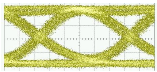
A typical 10Gbps transmitter eye diagram is shown in the figure below, and the time interval between the two crossing points of the eye diagram is 100 picoseconds.
QSFP+ Optical Module Reciever Performance Specification
- The sensitivity of the optical receiver, that is, the minimum optical power to ensure that the bit error rate is lower than 10E-12;
- Low light alarm and contact alarm function, that is, when the received optical power is less than a certain threshold, an alarm is sent to the main control terminal, and the alarm is cleared after the received optical power returns to normal.
- Jitter, the same as the transmitter;
- Rise and fall times, the same as the transmitter;
- Eye diagram template, same as transmitter.
A typical 10Gbps receiver eye diagram is shown below. Compared with the optical eye diagram, the difference in pure image is reflected in the position where the level of the receiving end eye diagram is 0 at half the height of the eye diagram. The optical eye diagram is expressed in terms of light energy intensity, and the electrical eye diagram is shown in the figure below, which is a high-frequency electrical signal oscillating on the 0-level line.
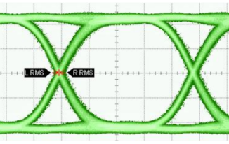
Rx Eye Diagram
Among the index parameters listed above, the core and most time-consuming, and also the main content discussed in this article, are as follows.
- Optical power and extinction ratio modulation at the optical transmitter;
- Parallel test of optical transmitter and receiver eye diagrams;
- Optical receiver sensitivity test.
Conclusion
This paper expounds the structural principle and main performance parameters of the QSFP+ optical module. A thorough and in-depth understanding of the structural principles and performance parameters of QSFP+ is essential for the next test and research work carried out by optical module manufacturers. QSFPTEK provides a full range of 40G QSFP modules, all modules have been strictly tested before leaving the factory to ensure high performance and high stability , welcome to inquire through sales@qsfptek.com.